XML
Laplace.T Root-locus Transient response Frecuency response


20 Problem A9.8 OGATA 4ed(Lead compensator, Bode plot)


    Let us calculate a compensator that satisfies the following requirements $K_{v}=20$, phase margin 50 and gain margin $\geq 10dB$. The open-loop system is the following:


    \begin{displaymath}G(s)=\frac{10}{s\cdot (s+1)}\end{displaymath}


    1. Let's calculate K y $G_{1}(jw)$

      \begin{displaymath}\lim_{s\rightarrow 0} s\cdot G(s) \cdot G_{c}(s)=K_{c}\cdot \alpha \cdot 10=K \cdot 10=20; K=\frac{20}{10}=2\end{displaymath}


      \begin{displaymath}G_{1}(jw)=\frac{2\cdot 10}{s\cdot (s+1)}=\frac{20}{s\cdot (s+1)}\end{displaymath}


    2. Let's calculate Bode plot of $G_{1}(jw)$

      \begin{displaymath}20\cdot log(20)=26.02\end{displaymath}


      Gain table:
      w   1  
      $\frac{1}{s}$ (-20) 0 (-20)
      $\frac{1}{(s+1)}$ (0) 0 (-20)
        (-20) 26.02 (-40)


      \begin{displaymath}dB\vert G_{1}(j0.1)\vert=26.02-20\cdot log(0.1)=46.02\end{displaymath}


      \begin{displaymath}dB\vert G_{1}(j10)\vert=26.02-40\cdot log(10)=-13.97\end{displaymath}

      Phase table:
      w 0.1   1   10  
      $\frac{1}{s}$ -90 (0) -90 (0) -90 (0)
      $\frac{1}{(s+1)}$ 0 (-45) -45 (-45) -90 (0)
        -90 (-45) -135 (-45) -180 (0)


      Bode plot by Scilab
      w1=[0.1 1 10];
      w2=[0.1 1 10];
      
      gdb1=20*log10(20)
      gdb(1)=gdb1-20*log10(0.1)
      gdb(2)=gdb1
      gdb(3)=gdb1-40*log10(10)
      
      a(1)=-90
      a(2)=-135
      a(3)=-180
      
      
      s=%s/(%pi*2);
      g=20/(s*(s+1))
      gs=syslin('c',g);
      w=logspace(-1,1,100);
      gsf=tf2ss(gs);
      [frq1,rep] =repfreq(gsf,w);
      [db,phi]=dbphi(rep);
      
      clf;
      subplot(2,1,1);
      plot2d(w,db,5,logflag="ln")
      plot2d(w1,gdb,2,logflag="ln")
      legends(['Exact','Calculated(approximated)'],[5,2],opt=1);
      xgrid;
      subplot(2,1,2);
      plot2d(w,phi,5,logflag="ln")
      plot2d(w2,a,2,logflag="ln")
      xgrid;
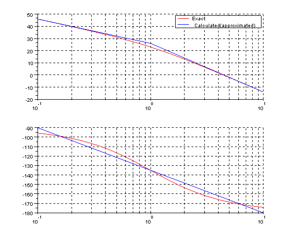
      
      Image ProblemaA9_8

      As you see we need a lead compensator to phase margin is 50

    3. Let's calculate the phase margin and compensator's phase ($\phi_{m}$)

      \begin{displaymath}dB\vert G_{1}(w_{c})\vert=dB\vert G_{1}(j1)\vert-40\cdot log (w_{c})=0\end{displaymath}


      \begin{displaymath}log (w_{c})=\frac{26.02}{40}\end{displaymath}


      \begin{displaymath}w_{c}=10^{\frac{26.02}{40}}=4.47\end{displaymath}


      \begin{displaymath}\lfloor{G_{1}(j4.47)}=-135-45*log10(w_{c})=-164.27\end{displaymath}


      \begin{displaymath}Phasemargin=180-164.278=15.72\end{displaymath}


      \begin{displaymath}\phi_{m}=50-15.72+5\approx 40\end{displaymath}


    4. We calculate the $\alpha$ of compensator

      \begin{displaymath}G_{c}(s)=K_{c}\cdot \frac{s+\frac{1}{T}}{s+\frac{1}{\alpha \cdot T}}\end{displaymath}


      \begin{displaymath}sen(\phi_{m})=\frac{1-\alpha}{1+\alpha}\end{displaymath}


      \begin{displaymath}\alpha=\frac{1-sen(\phi_{m})}{1+sen(\phi_{m})}=0.22\end{displaymath}


    5. We calculate the T of compensator

      \begin{displaymath}dB\vert G_{1}(w)\vert=-20\cdot log(\frac{1}{\sqrt{\alpha}})=-6.48\end{displaymath}


      \begin{displaymath}26.02-40\cdot log(w)=-6.48\end{displaymath}


      \begin{displaymath}log(w)=\frac{26.02+7.19}{40}\end{displaymath}


      \begin{displaymath}w=6.49\end{displaymath}

      This value 6.49 is the crossover gain frequency.

      \begin{displaymath}w=\frac{1}{\sqrt{\alpha}\cdot T}\end{displaymath}


      \begin{displaymath}T=\frac{1}{\sqrt{ \alpha}\cdot w}=\frac{1}{\sqrt{0.22}\cdot 6.49}=0.32\end{displaymath}


      \begin{displaymath}G_{c}(s)=K_{c}\cdot \frac{s+\frac{1}{T}}{s+\frac{1}{\alpha \cdot T}}=K_{c}\cdot \frac{s+3.08}{s+13.7}\end{displaymath}


    6. We calculate the $K_c$ of compensator

      \begin{displaymath}K=K_{c}\cdot \alpha; K_{c}=\frac{K}{\alpha}=\frac{2}{0.22}=8.9\end{displaymath}

      The compensator is:

      \begin{displaymath}G_{c}(s)=8.9 \cdot \frac{s+3.08}{s+13.07}\end{displaymath}


    Calculations, checks and Bode plot by Scilab:
    gdb1=20*log10(20)
    gdb(1)=gdb1-20*log10(0.1)
    gdb(2)=gdb1
    gdb(3)=gdb1-40*log10(10)
    
    a(1)=-90
    a(2)=-135
    a(3)=-180
    
    wcg=10^(gdb1/40)
    awcg=a(2)-45*log10(wcg)
    mf=180+awcg
    pm=50-mf+5
    
    aux1=pm*2*%pi/360;
    aux2=sin(aux1);
    alp=(1-aux2)/(1+aux2)
    aux3=-20*log10(1/(sqrt(alp)))
    nwcg=10^((gdb1-aux3)/40)
    T=1/(sqrt(alp)*nwcg)
    zc=1/T
    pc=1/(alp*T)
    kc=2/alp
    
    
    s=%s/(2*%pi);
    g=10/((s+0.000001)*(s+1))
    gc=kc*(s+zc)/(s+pc);
    gt=g*gc;
    gts=syslin('c',gt);
    [mg,fcp]=g_margin(gts)
    [mp,fcg]=p_margin(gts)
    
    
    gc2=9.5238*(s+2.9787)/(s+14.1842);
    gt2=g*gc2;
    gs=syslin('c',2*g);
    gcs=syslin('c',gc);
    gcs2=syslin('c',gc2);
    gts=syslin('c',gt);
    gts2=syslin('c',gt2);
    clf();
    bode([gs;gcs;gts;gts2;gcs2],['Gc(jw) Book';'G(jw)*Gc(jw) Book';'G(jw)*Gc(jw)'
    ;'Gc(jw)';'G1(jw)' ]);
    
    Results:
    -->[mg,fcp]=g_margin(gts)
     fcp  =
     
         []
     mg  =
     
       Inf  
     
    -->[mp,fcg]=p_margin(gts)
     fcg  =
     
        6.4389613  
     mp  =
     
        48.099889
    

    As you see the phase margin is 48 when we had to give 50 should have added 12 instead of 5 to calculate the $ \ phi_ (m) $. The gain margin is infinite because the phase does not cut to -180, is always above.
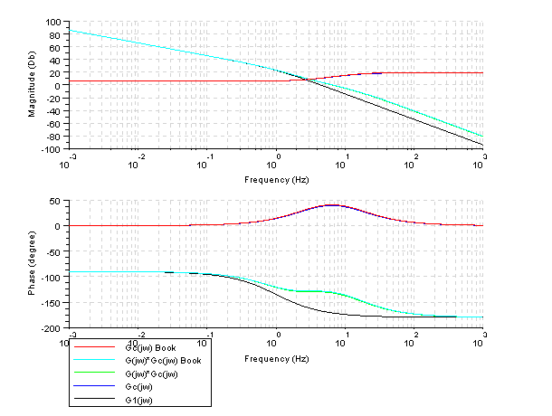
    Image ProblemaA9_8b
    Let's draw the unit-step response by Scilab
    Scilab program:
    s=%s;
    g=10/(s*(s+1))
    gc=8.9*(s+3.07)/(s+13.7);
    gt=g*gc;
    gc2=9.5238*(s+2.9787)/(s+14.1842);
    gt2=g*gc2;
    glc=g /. 1;
    gtlc=gt /. 1;
    gtlc2=gt2 /. 1;
    gs=syslin('c',glc);
    gcs=syslin('c',gtlc);
    gcs2=syslin('c',gtlc2);
    t=0:0.1:6;
    y=csim('step',t,gs);
    y1=csim('step',t,gcs);
    y2=csim('step',t,gcs2);
    clf();
    plot(t,y,'k');
    plot(t,y1,'b');
    plot(t,y2,'g');
    xtitle('Unit-step response','t (seg)','y(t)');
    legends(['G(s)';'Gc(s)*G(s)';'Book'],[1,2,3],opt=1);
    xgrid;
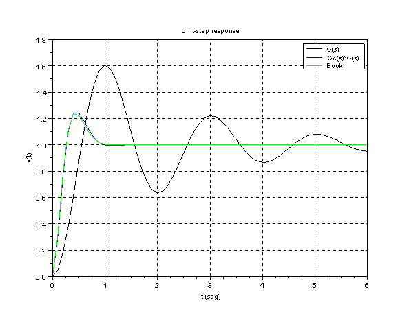
    
    Image ProblemaA9_8c
    Let's draw the unit-ramp response by Scilab
    Scilab program:
    s=%s;
    g=10/(s*(s+1))
    gc=8.9*(s+3.07)/(s+13.7);
    gt=g*gc;
    gc2=9.5238*(s+2.9787)/(s+14.1842);
    gt2=g*gc2;
    glc=g /. 1;
    gtlc=gt /. 1;
    gtlc2=gt2 /. 1;
    gs=syslin('c',glc);
    gcs=syslin('c',gtlc);
    gcs2=syslin('c',gtlc2);
    t=0:0.1:3;
    y=csim(t,t,gs);
    y1=csim(t,t,gcs);
    y2=csim(t,t,gcs2);
    clf();
    plot(t,t,'r');
    plot(t,y,'k');
    plot(t,y1,'b');
    plot(t,y2,'g');
    xtitle('Ramp response','t (seg)','y(t)');
    legends(['Ramp';'G(s)';'Gc(s)*G(s)';'Book'],[color('red'),1,2,3],opt=1);
    xgrid;
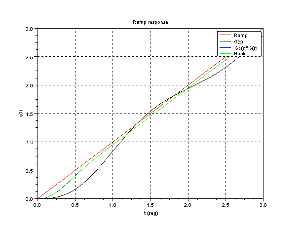
    
    Image ProblemaA9_8d